
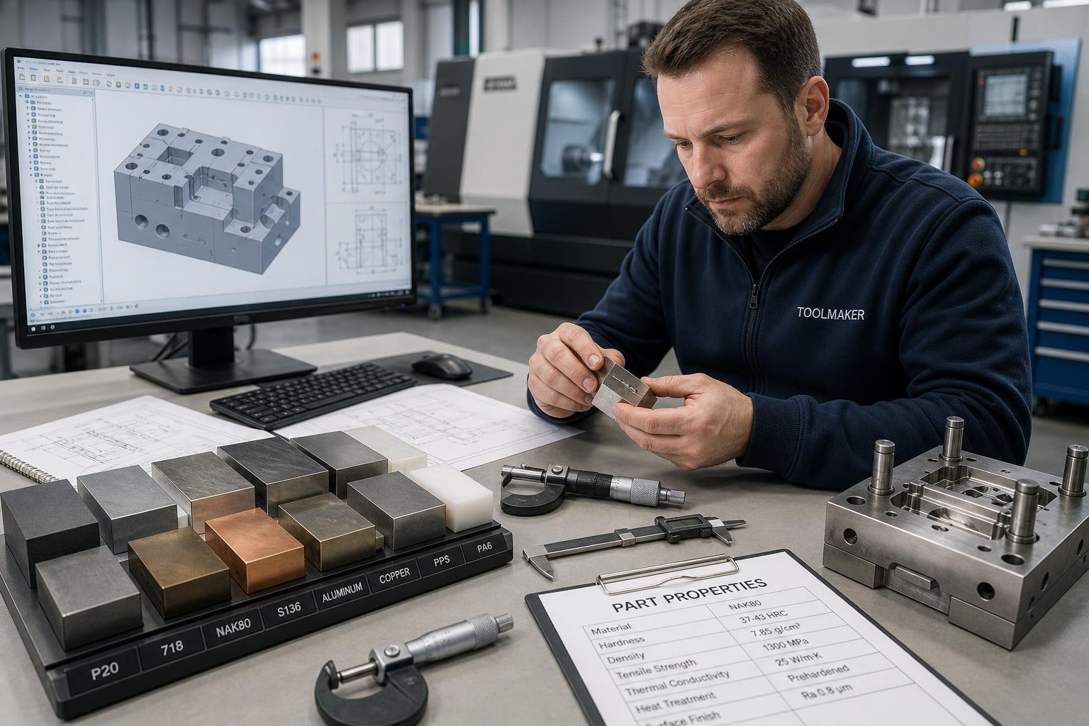
What Is the Toolmaking Process? From Design to First Shot Explained
Toolmaking bridges the gap between a product idea and actual manufacturing. The toolmaking process involves designing specialised equipment, selecting appropriate materials, machining precise components, and conducting trials to ensure tools can produce parts that meet exact specifications. Without proper tooling, manufacturers cannot create consistent, high-quality products at scale.
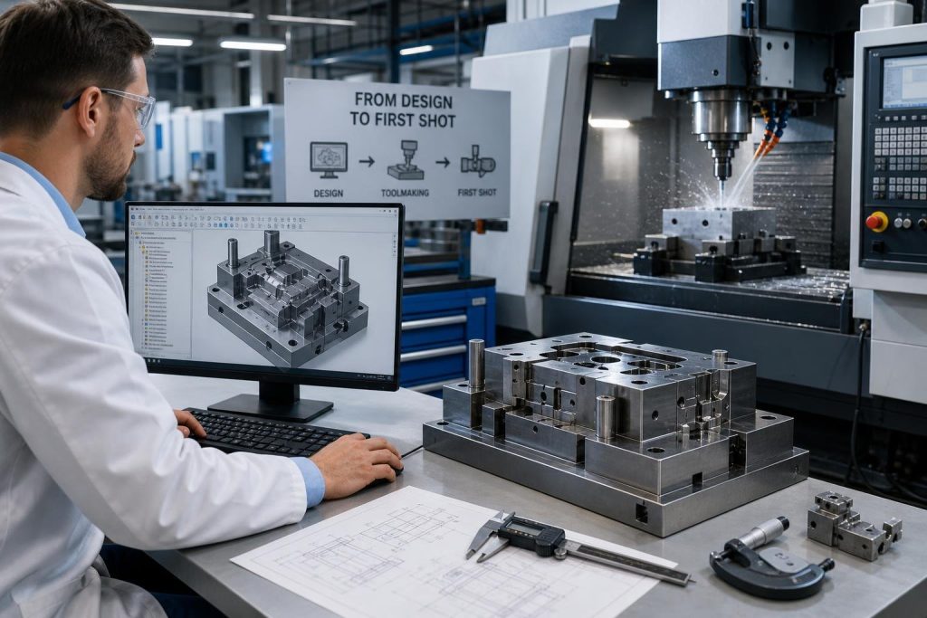
The toolmaking process starts with defining objectives and progresses through multiple stages including design, material preparation, machining, quality control, and testing. Each stage requires careful attention to prevent costly errors like material waste, machine downtime, and rejected parts. Understanding this process helps you make better decisions about timelines, costs, and manufacturing partners.
Whether you’re developing your first product or refining an existing design, knowing how tools move from concept to first production shot gives you realistic expectations. The journey involves prototyping and validation through T1 and T2 trials, fine-tuning cutting parameters, and addressing any issues before full-scale production begins.
Key Takeaways
- Toolmaking transforms product designs into physical manufacturing equipment through careful planning, material selection, and precision machining
- The process includes multiple testing phases to validate tool performance and make adjustments before production begins
- Proper toolmaking prevents expensive manufacturing problems and ensures consistent product quality throughout production
Foundations of Toolmaking
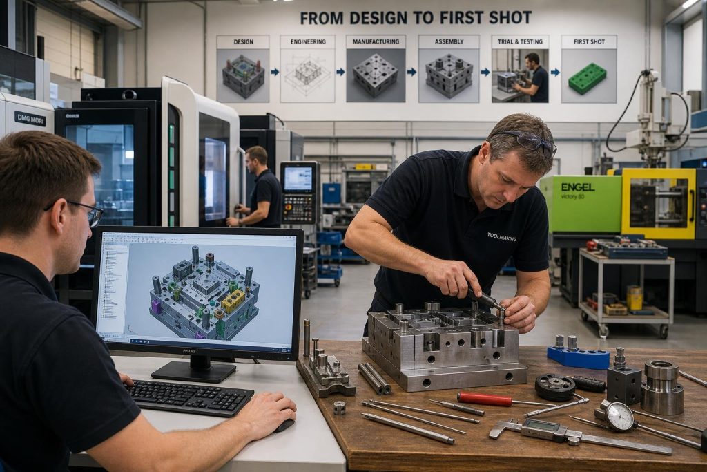
Toolmaking centres on creating precise equipment that shapes, cuts, or forms materials into finished products. The field combines technical knowledge with hands-on skills to produce tools that enable mass production across industries.
Key Concepts and Definitions
Tool making refers to manufacturing tools used to produce other products. These tools include metal forming rolls, cutting implements like lathe bits and milling cutters, and fixtures that hold workpieces during fabrication.
Tooling encompasses the complete set of equipment needed for manufacturing operations. You’ll find tooling in stamping presses, injection moulding machines, and metal forming equipment. The tools must meet tight tolerances to ensure consistent product quality.
Tool and die manufacturing combines design expertise with precision machining. Your manufacturing partner uses computer-aided design software to create detailed specifications. The process demands understanding of materials, cutting operations, and measurement techniques to achieve the required accuracy.
Historical Evolution and Industry Importance
Tool and die work evolved from manual craftsmanship to computer-controlled processes. Early toolmakers relied on hand tools and basic machines. Modern facilities now use CNC equipment and electrical discharge machining for complex geometries.
The industry supports mass production across automotive, aerospace, and consumer goods sectors. Without precision tooling, manufacturers cannot produce identical parts at scale. Your ability to deliver consistent products depends on quality tools that maintain specifications through thousands of production cycles.
Manufacturing processes advanced as toolmaking technology improved. Computer integration reduced human error whilst increasing production speed. The shift from manual to automated operations changed how you approach tool design and fabrication.
Distinction Between Tools, Dies, and Moulds
Tools are general-purpose implements for cutting, shaping, or forming materials. They include drill bits, cutting blades, and forming rolls used across various manufacturing operations.
Dies are specialised tools that cut or shape materials through pressing action. You’ll encounter three main types:
- Stamping dies cut and form sheet metal into precise components
- Forging dies shape heated metal under high pressure
- Drawing dies pull wire or tubing through shaped openings
Moulds create parts by filling a cavity with material that hardens into the desired shape. Injection moulds form plastic components whilst casting moulds produce metal parts. The mould’s internal cavity defines your final product’s external features.
Toolmaking Design Principles
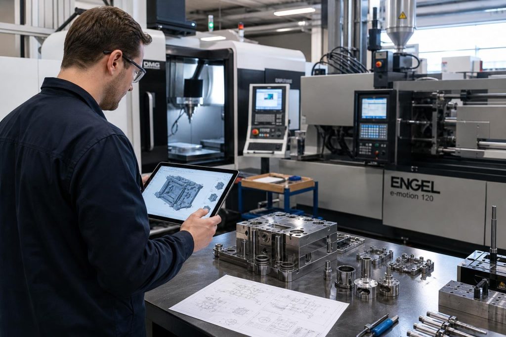
Successful toolmaking begins with thorough needs analysis and follows established design principles that ensure precision, safety, and manufacturability. Documentation, simulation, and adherence to industry standards form the foundation of reliable tool production.
Needs Analysis and Problem Definition
Before any design work begins, you must clearly define what the tool needs to accomplish. This involves understanding the specific manufacturing process, the materials being worked with, and the production volumes required. You’ll need to identify constraints such as budget limitations, timeline requirements, and the available manufacturing equipment.
During this phase, you should gather input from all stakeholders including production staff, quality teams, and maintenance personnel. Their practical experience often reveals critical requirements that might otherwise be overlooked. You’ll also need to consider the tool’s operational environment, including temperature ranges, exposure to chemicals or contaminants, and maintenance access requirements.
A thorough problem definition prevents costly redesigns later in the process. You should document all requirements clearly, distinguishing between essential features and desirable ones.
Iterative Design and Planning
The design phase involves creating detailed blueprints using CAD software that allow you to visualise the tool in three dimensions. You’ll work through multiple design iterations, refining the geometry, material specifications, and manufacturing approach with each version.
Simulation software plays a vital role during this stage. You can test how the tool will perform under various conditions without building physical prototypes. This includes stress analysis, thermal behaviour, and wear patterns that help you identify potential weaknesses before fabrication begins.
Your design and planning must account for manufacturing feasibility. You should consider how the tool will be machined, what tolerances are achievable, and which features require special processes like EDM. Collaboration between designers and machinists during this phase ensures the design is practical to produce.
Design Specifications and Documentation
Comprehensive documentation is essential for successful tool production. Your design specifications must include precise dimensions, material callouts, surface finish requirements, and assembly instructions. Every tolerance should be clearly defined with appropriate geometric dimensioning and tolerancing symbols.
You need to create detailed drawings that communicate all critical information to the manufacturing team. These should include section views, detail callouts, and notes about special processes or inspection requirements. Bill of materials documentation ensures all components are specified correctly.
Key documentation elements include:
- Detailed part drawings with full dimensioning
- Assembly drawings showing component relationships
- Material specifications and heat treatment requirements
- Surface finish and coating specifications
- Inspection and quality control procedures
Industry Standards and Safety
Your toolmaking process must comply with relevant industry standards that ensure quality and safety. ISO 9001 certification requirements often govern how you document processes, maintain records, and implement quality assurance procedures. These standards help you maintain consistency and traceability throughout the manufacturing process.
Safety considerations must be integrated into your design from the start. You should identify potential hazards such as pinch points, sharp edges, or heavy components that require lifting assistance. Guards, safety interlocks, and emergency stop features may need to be incorporated depending on the tool’s application.
Quality assurance protocols should be established during the design phase. You’ll need to define critical dimensions, establish inspection methods, and set acceptance criteria. This includes determining which features require statistical process control and what measurement equipment is needed for verification.
Digital Tools and Modelling
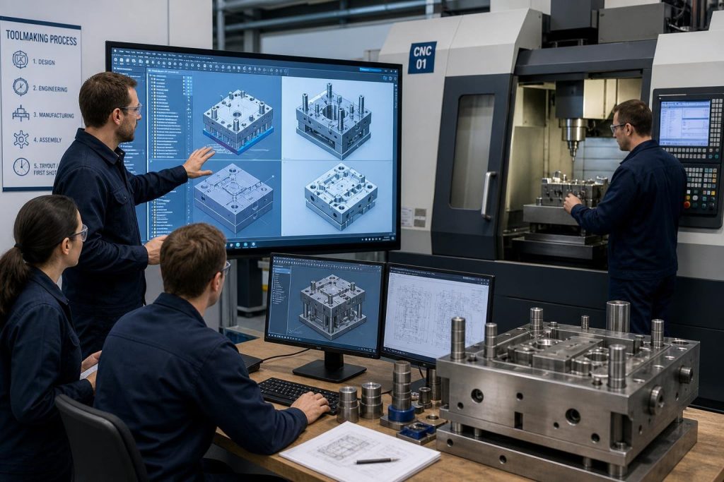
Modern toolmaking relies on advanced software to create precise designs and test them before physical production begins. CAD and CAM systems work together to transform concepts into detailed specifications, while simulation technology helps identify potential problems early in the process.
Using CAD and CAM Software
You’ll find that CAD (computer-aided design) software forms the foundation of modern tool manufacturing. This software allows you to create detailed technical drawings and specifications on your computer. CAM (computer-aided manufacturing) software then converts these designs into instructions that machines can follow.
When you use CAD software, you can modify designs quickly without starting from scratch. This saves time and reduces errors compared to hand-drawn plans. CAM software takes your finalised CAD files and generates toolpaths for CNC machines and other automated equipment.
The combination of CAD and CAM creates a seamless workflow. You design the tool digitally, validate it through testing, and then produce it using automated machinery that follows your exact specifications.
Development of 3D and CAD Models
Your toolmaking process begins with creating 3D models that represent every detail of the finished tool. Designers use CAD software to create detailed 3D models of the desired mould, allowing you to visualise the tool from every angle before manufacturing starts.
These 3D models include precise measurements, material specifications, and tolerances. You can rotate the model, zoom in on specific features, and check how different components fit together. This level of detail helps you spot design flaws that might not be obvious in 2D drawings.
CAD models also serve as the master reference throughout production. You can share these digital files with team members, suppliers, and clients to ensure everyone understands the specifications exactly as you intended them.
Design Validation and Simulation
Simulation software lets you test your tool designs virtually before committing to physical production. You can analyse how materials will flow, where stress points might develop, and whether the tool will perform as expected under real-world conditions.
This iterative design process helps you refine your tool through multiple versions. You make adjustments based on simulation results, then run new tests to verify improvements. Each cycle brings you closer to an optimised design.
Validation through simulation reduces the risk of costly mistakes. You can identify problems like weak points, excessive wear areas, or dimensional issues whilst they’re still easy to fix. This approach saves both time and money compared to discovering these issues after manufacturing begins.
Material Selection and Part Properties
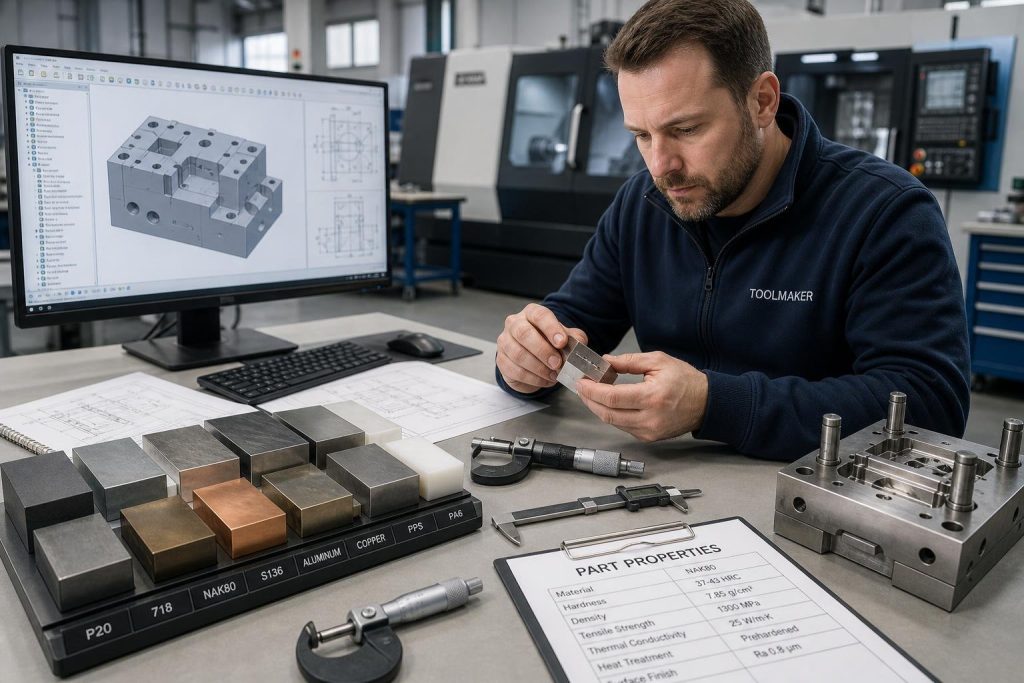
The materials you choose for toolmaking directly affect the tool’s performance, lifespan, and production quality. Proper selection requires balancing mechanical properties, manufacturing constraints, and the specific demands of your production environment.
Common Toolmaking Materials
Tool steels dominate toolmaking because they offer superior hardness, wear resistance, and dimensional stability under repeated use. P20 steel serves as a workhorse for general-purpose moulds, providing good machinability and moderate hardness suitable for medium production runs. H13 tool steel excels in applications requiring heat resistance and toughness, making it ideal for die casting and hot forming operations.
For high-volume production, hardened tool steels like S7 and D2 deliver exceptional wear resistance. Stainless steel variants such as 420 and 440C combine corrosion resistance with adequate hardness for moulds producing medical devices or food packaging. Aluminium serves niche applications where rapid heat dissipation matters more than durability, whilst beryllium copper alloys provide thermal conductivity superior to steel in cooling-critical areas like core pins and inserts.
Selection Criteria
Your material choice must align with expected production volumes, part geometry, and the plastic resins you’ll process. Material selection involves evaluating mechanical properties, cost constraints, and manufacturing requirements simultaneously.
Key selection factors include:
- Production volume — High-volume runs demand harder, more wear-resistant materials
- Part complexity — Intricate geometries require materials with superior machinability
- Resin abrasiveness — Glass-filled plastics necessitate harder tool surfaces
- Surface finish requirements — Mirror finishes demand materials that polish well
- Budget constraints — Raw materials and heat treatment costs affect total investment
Pre-hardened steels reduce lead times by eliminating post-machining heat treatment, though they sacrifice ultimate hardness. Through-hardened materials achieve superior wear resistance but require careful planning to accommodate distortion during heat treatment processes.
Thermal Conductivity and Corrosion Resistance
Thermal conductivity determines how efficiently your tool removes heat from molten plastic during each cycle. Poor heat transfer extends cycle times and can cause part defects like warpage or sink marks. Standard tool steels typically exhibit thermal conductivity around 20-30 W/m·K, whilst aluminium reaches 160-200 W/m·K.
Beryllium copper alloys bridge this gap at 80-120 W/m·K, making them valuable for hot spots in otherwise steel tools. Corrosion resistance becomes critical when processing hygroscopic resins like nylon or PVC, which release corrosive gases during moulding. Stainless tool steels or surface treatments like chrome plating protect against chemical attack that would otherwise pit and damage mould surfaces.
Environmental Considerations
Modern toolmaking increasingly accounts for sustainability alongside performance. Material selection affects energy consumption through thermal properties—better heat transfer means shorter cooling times and lower energy use per cycle. Recyclable tool steels reduce environmental impact at end-of-life, whilst some manufacturers now specify materials based on their carbon footprint during production.
Durability itself serves as an environmental factor. Longer-lasting tools require fewer replacements, reducing raw material consumption and manufacturing waste over the production lifetime. Surface treatments can extend tool life without requiring exotic base materials, offering a practical compromise between performance and environmental responsibility.
Machining and Fabrication Techniques

Machining and fabrication transform raw materials into precise tooling components through cutting, shaping, and forming processes. These techniques require specialised equipment and skilled operators to achieve the tight tolerances essential for reliable tool performance.
CNC Machining and Milling
CNC machining provides high accuracy and repeatability through computer-controlled operations that follow programmed tool paths. You’ll find CNC mills removing material from blocks of tool steel to create die cavities, punch holders, and complex geometries that would be impossible to achieve manually.
The milling process uses a rotating cutting tool that moves across multiple axes to shape your workpiece. Modern CNC machining centres can operate on five axes simultaneously, allowing you to machine intricate features without repositioning the part.
Key advantages of CNC milling include:
- Consistent dimensional accuracy within microns
- Complex 3D surface capabilities
- Reduced setup time for repeat jobs
- Automated operation for high-volume production
Your choice of cutting tools, speeds, and feeds directly affects surface finish quality and tool life. Coolant systems help manage heat and remove chips during the machining process.
EDM and Electrical Discharge Machining
EDM uses electrical sparks to erode material from hardened tool steels that are too hard for conventional cutting tools. You create shapes by controlled electrical discharges between an electrode and your workpiece, both submerged in dielectric fluid.
Wire EDM threads a thin brass wire through the material to cut intricate profiles and internal features. This technique excels at producing sharp corners and precise slots in punches and die blocks. Sinker EDM uses shaped electrodes to burn cavities into solid metal, ideal for complex die impressions and detailed surface textures.
The process leaves no mechanical cutting forces on your workpiece, preventing distortion in delicate features. You can machine hardened tools after heat treatment, eliminating the risk of warping during hardening.
Turning, Drilling, and Grinding
Turning rotates your workpiece whilst moving a cutting tool against it to create cylindrical features like punches, guide posts, and bushings. Lathes handle both external diameters and internal bores with precision.
Drilling creates holes for dowel pins, fasteners, and coolant passages throughout your tool assembly. You’ll use specialised drills and reamers to achieve accurate hole sizes and positions that ensure proper alignment.
Grinding operations include:
- Surface grinding for flat, parallel surfaces on die plates
- Cylindrical grinding for precise punch diameters
- Tool and cutter grinding for sharpening cutting edges
Precision grinding removes small amounts of material to achieve your final dimensions and superior surface finishes. You typically grind components after heat treatment to correct any distortion and reach final tolerances.
Additive Manufacturing and 3D Printing
Additive manufacturing builds components layer by layer from digital designs, offering rapid prototyping capabilities for tool development. You can test conformal cooling channels and complex geometries before committing to traditional machining.
Metal 3D printing produces functional tool inserts from powdered alloys using laser or electron beam fusion. This technology allows you to create cooling channels that follow the contours of your die cavity, improving temperature control and cycle times.
Polymer printing helps you validate tool designs through physical models before fabrication begins. You’ll identify potential assembly issues and test part ejection sequences at a fraction of traditional prototyping costs.
The finishing requirements for additive parts vary based on application, with some surfaces needing additional machining or polishing to meet production standards.
Tool Assembly and Alignment
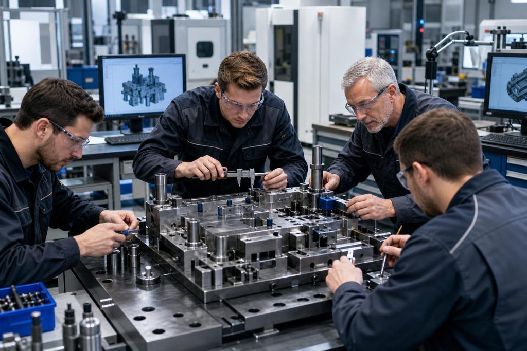
The assembly process requires careful attention to positioning and fit of each component. Proper alignment through dowel pins, guideposts, and bushings ensures your tool operates reliably during production runs.
Assembly Procedures and Dowel Pins
Your tool assembly begins with establishing fixed reference points that maintain alignment throughout the tool’s life. Dowel pins serve as the primary alignment mechanism between tool halves and components.
You must install dowel pins before any other fasteners go in. These hardened steel pins fit into precisely reamed holes on both mating surfaces. The tight fit prevents any lateral movement between components during press cycles.
Standard dowel pin placement:
- Minimum of two pins per assembly
- Positioned diagonally across the tool face
- Located as far apart as the tool size permits
- Sized to match hole tolerances within 0.0005 inches
Component integration follows a specific sequence during assembly. You’ll position the lower die components first, then align the upper die assembly using the installed dowel pins as guides. Each fastener requires proper torque specifications to prevent loosening during operation.
Guideposts, Bushings, and Stripper Plates
Guideposts and bushings provide vertical alignment between moving tool sections. You’ll find these components on the outer edges of most stamping dies, where they guide the punch holder during each press stroke.
The guidepost slides through a bushing mounted in the die shoe. This sliding action must remain smooth across millions of cycles. You need to select bushings made from bronze or oil-impregnated materials that resist wear and reduce friction.
Your stripper plate holds the metal strip flat whilst ejecting it from the punch after each cut. The plate mounts on springs or nitrogen cylinders that provide consistent pressure. Proper stripper plate alignment prevents material buckling and ensures clean part ejection.
Progressive, Compound, and Transfer Dies
Progressive dies perform multiple operations as the material strip advances through stations. Your assembly must maintain precise spacing between each station to ensure features align correctly on the finished part.
Compound dies complete multiple operations in a single press stroke at one station. You’ll assemble these tools with punches and dies stacked vertically, requiring exact parallelism between cutting surfaces.
Transfer dies move individual blanks between stations using mechanical fingers or rails. Your assembly needs accurate positioning mechanisms at each station to catch and release parts reliably. The tool and die process for transfer systems demands rigorous precision engineering throughout assembly.
Finishing, Surface Treatment, and Maintenance
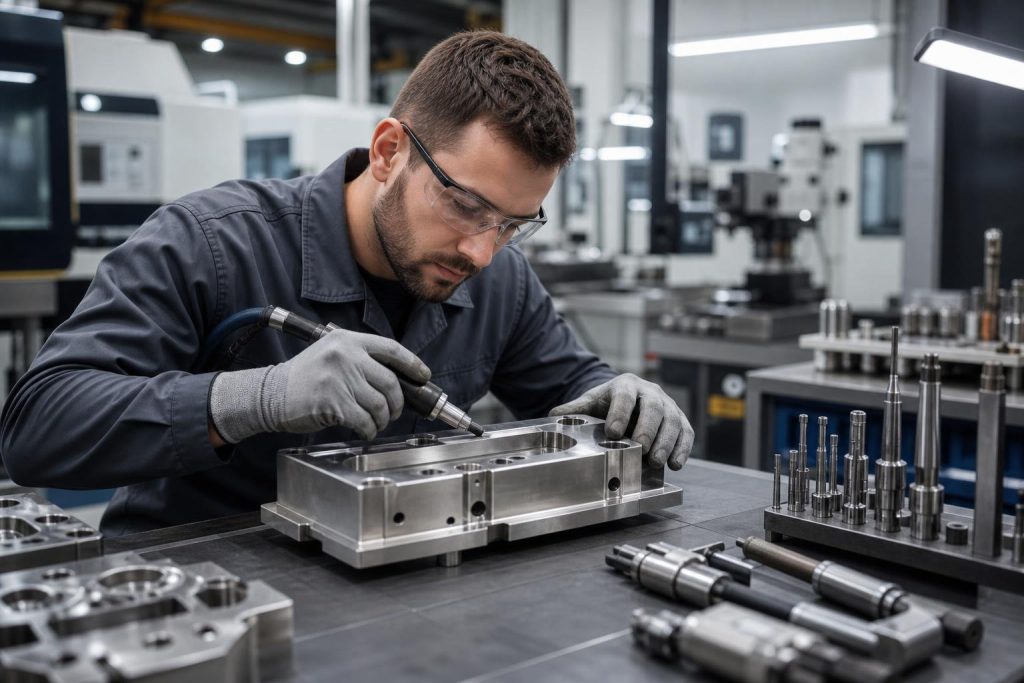
After machining completes, tools require proper finishing to achieve the right surface quality and protection. Regular upkeep extends tool life and maintains performance throughout production runs.
Surface Finishing and Polishing
Surface finishing improves both the appearance and function of your tooling. Grinding helps achieve smooth and flat surfaces within tight tolerances, which is essential for precision tooling work.
Polishing creates an even smoother finish that reduces friction during moulding operations. This process removes minor imperfections left from earlier machining steps. A polished surface also makes it easier to eject parts from the mould cavity.
You might also need buffing or honing depending on your tool’s requirements. These finishing processes refine the surface quality further and help meet specific functional needs. The right surface finish directly affects how well your tool performs and how long it lasts.
Deburring and Trimming
Deburring removes sharp edges and unwanted material left behind after machining. These burrs can damage parts, create safety hazards, and affect how accurately your tool functions.
Manual deburring works for simple tools, whilst automated methods handle complex geometries more efficiently. You need to inspect all edges, cavities, and parting lines carefully. Even small burrs can cause problems during production.
Trimming ensures all dimensions meet your specifications exactly. This step removes any excess material and refines critical features. Proper deburring and trimming prevent defects in your moulded parts and protect the tool from premature wear.
Regular and Preventive Maintenance
Your tooling needs consistent care to maintain performance. Regular maintenance includes cleaning, inspection, and lubrication after each production run or at set intervals.
Check for wear patterns, cracks, or damage on critical surfaces. Look at ejector pins, slides, and other moving components for signs of deterioration. Clean out any residue or buildup that could affect part quality.
Preventive maintenance catches small issues before they become costly failures. Replace worn components before they damage other tool parts. Keep detailed records of maintenance activities and any problems you find. This documentation helps you spot patterns and plan future upkeep more effectively.
Tool Life Optimisation
Extending tool life requires attention throughout its working period. Proper surface treatments improve resistance to corrosion, oxidation, and wear, which protects your investment over thousands of cycles.
Monitor cycle counts and part quality trends to predict when maintenance is needed. Adjust process parameters if you notice changes in performance. Temperature, pressure, and cycle time all affect how quickly your tool wears.
Store tools properly when not in use. Apply rust preventatives to vulnerable surfaces and keep tools in controlled environments. Document any modifications or repairs so future users understand the tool’s history. Smart maintenance practices can double or triple your tool’s productive life whilst maintaining consistent part quality.
Inspection, Testing, and Quality Control
Quality control in toolmaking ensures that manufactured tools meet precise specifications and perform correctly before production begins. Inspection methods verify dimensions and tolerances, whilst testing confirms that the tool functions as intended under actual operating conditions.
Measurement and Tolerances
Tolerances define the acceptable range of variation in a tool’s dimensions. Your toolmaker must verify that every critical dimension falls within the specified tolerance range to ensure proper function.
Dimensional stability is crucial because even small deviations can cause problems during production. You need to check measurements at multiple stages of manufacturing, not just at the end. This catches errors early before they become costly.
Common measurement tools include micrometres, callipers, and gauges. These instruments measure features like hole diameters, wall thicknesses, and surface profiles. Your team records all measurements to create a quality record for the tool.
Tight tolerances often require measurements accurate to within thousandths of a millimetre. This level of precision ensures consistent product quality when the tool enters production.
Use of Coordinate Measuring Machines
A coordinate measuring machine (CMM) provides highly accurate three-dimensional measurements of complex tool geometries. The CMM uses a probe to touch specific points on the tool and records their exact positions in space.
You can measure features that are difficult or impossible to check with hand tools. The CMM software compares actual measurements against your CAD model to identify any deviations. This quality inspection process generates detailed reports showing exactly where the tool meets or exceeds specifications.
Modern CMMs can measure hundreds of points automatically. This creates a complete picture of the tool’s accuracy. You receive data on form, position, and dimensional accuracy for every critical feature.
The CMM inspection typically happens after major machining operations are complete. This confirms the tool is ready to move forward in the manufacturing process.
Functional Testing and Validation
Functional testing verifies that your tool performs correctly under realistic conditions. You run the tool through actual production cycles to check for problems before committing to full production.
First article inspection examines the initial parts produced by the tool. You check whether these parts meet all design requirements and quality standards. This testing reveals issues like improper material flow, cooling problems, or ejection difficulties.
Your team typically runs multiple test cycles. Each cycle helps identify and correct problems. You adjust the tool based on test results until it produces parts that meet specifications consistently.
Testing also evaluates cycle time, tool wear, and ease of operation. These factors affect production efficiency and long-term tool performance.
Documentation and Quality Assurance
Quality assurance requires thorough documentation of all inspections and tests. You create records that prove the tool meets specifications and regulatory requirements.
Your documentation includes measurement data, inspection reports, and test results. These records provide traceability if quality issues arise later. Quality control documentation also helps you improve future tool designs by identifying common problems.
Inspection certificates confirm that the tool passed all quality checks. You receive detailed reports showing dimensions, tolerances, and test outcomes. Many industries require this documentation for compliance purposes.
Your toolmaker should maintain records throughout the entire manufacturing process. This creates a complete quality history for the tool from initial machining through final approval.
Prototyping and Initial Production
The shift from design to physical production requires careful prototype development and testing to validate your tool’s performance. This phase involves creating initial samples, gathering feedback, and refining the design before committing to full-scale manufacturing.
Prototype Development and Testing
Prototype tooling creates molds and dies quickly to produce initial parts or small batches. You can choose between direct prototype tooling, which uses 3D printing or CNC machining to build tools straight from digital models, or indirect methods that require a master pattern first.
The prototypes you create during this stage need to undergo functional testing. These parts should closely mimic production characteristics so you can evaluate real-world performance. Testing prototypes helps you identify design flaws like sinks, burns, and flow marks before they become costly problems in high-volume production.
Direct prototype tooling reduces lead times significantly because it eliminates intermediary steps. Indirect tooling works better when you need more durable materials or plan to create multiple molds from one master pattern.
User Feedback and Iterative Improvement
Your prototype development process should include multiple iterations based on testing results and feedback. This flexibility allows you to modify designs quickly and explore different options without significant cost increases.
Each iteration brings your tool closer to meeting specifications. You might discover that certain features need adjustment or that materials perform differently than expected. Small batch production during this phase lets you test variations and confirm improvements before scaling up.
Industries with strict safety regulations particularly benefit from thorough prototype testing. You need to verify that your tool produces parts meeting all requirements before moving forward.
From Prototype to First Shot
The transition from prototype to first shot marks when your tool moves into actual production. You’ve validated the design through testing and incorporated necessary changes from your iterations.
Small batch production serves as the final validation step before high-volume production begins. Your first shots confirm that the tool performs consistently and produces parts within tolerance. This stage may reveal minor adjustments needed for optimal performance, but major design changes should be complete.
Lead times between prototype approval and first shot depend on tool complexity and manufacturing methods. Proper prototype development reduces these timelines by catching issues early.
Tooling for Injection Moulding and Mass Production
The mould itself determines how efficiently you can produce plastic parts at scale. Material selection, design complexity, and production volume requirements all shape your tooling strategy and long-term manufacturing costs.
Injection Mould Design and Materials
Your injection mould design begins with CAD software and simulations to predict how molten plastic flows, cools, and solidifies. These digital tools help you identify potential issues like air traps or uneven cooling before fabrication starts.
Steel moulds work best for high-volume production because they withstand hundreds of thousands of cycles. P-20 steel offers good machinability for general-purpose moulds, while NAK80 provides superior wear resistance for high-precision work. Aluminium moulds cost less and machine faster, making them suitable for low-volume runs or prototyping.
Surface treatments like nitriding extend mould life by improving wear resistance. Cooling line placement within the mould affects cycle time and part quality—strategic positioning ensures uniform temperature distribution and prevents warpage. Your mould design must balance injection pressure with tight tolerances to fill complex geometries without causing flashing or short shots.
Tooling Solutions for Plastic Parts
Multi-cavity moulds produce several identical parts per cycle, dramatically reducing per-unit costs during mass production. Family moulds create different parts simultaneously, which proves useful when components need assembly together.
Specialised tooling techniques expand your design possibilities:
- Overmoulding combines two materials in one part for enhanced grip or protection
- Insert moulding integrates metal components like threads directly into plastic
- Gas-assist moulding creates hollow sections in thick areas to reduce material use
Three-plate moulds offer greater gating flexibility for parts requiring cosmetic surfaces. Unscrewing moulds contain mechanisms to produce internal or external threading automatically.
Transitioning to Mass Production
Before full production begins, you need design validation through computer simulations and physical test shots. These trial runs establish optimal parameters and identify defects related to mould flow or cooling efficiency.
Regular maintenance extends your tooling life and ensures consistent quality throughout production. Clean moulds regularly to prevent material build-up. Inspect for wear and replace components like ejector pins proactively.
High-quality injection moulding tooling represents a significant upfront investment but produces millions of parts with identical precision. Your manufacturing process benefits from reduced cycle times, minimal waste, and fewer defects when tooling performs correctly. Track mould wear over time to anticipate maintenance needs and avoid unexpected downtime during long production runs.
Continuous Improvement and Manufacturing Excellence
Toolmakers who excel don’t stop at first article approval. They build feedback systems that capture real-world performance data, apply lean principles to eliminate waste, and design tooling that scales efficiently from prototype to high-volume production.
Feedback Loops and Iterative Design
Your tooling partner should establish clear channels for capturing production data after the first shot. This includes tracking cycle times, defect rates, and any processing issues that emerge during initial runs.
Quality circles bring together tool designers, production staff, and quality engineers to review performance metrics. These teams identify problems early and recommend modifications before full production begins.
Key feedback mechanisms include:
- Daily production reports showing part quality and cycle efficiency
- Wear pattern analysis on critical tool surfaces
- Temperature mapping to identify hot spots or cooling inefficiencies
- Dimensional inspection data comparing first shots to production runs
The PDCA cycle (Plan-Do-Check-Act) provides a framework for testing modifications. You might adjust cooling line placement, change gate locations, or modify ejection systems based on actual performance data rather than assumptions.
Lean Manufacturing Practices
Lean manufacturing principles eliminate waste throughout the toolmaking process. Your manufacturing partner should apply techniques like 5S workplace organisation to maintain clean, efficient tool rooms where equipment and materials are easy to locate.
Standard work procedures ensure every technician machines components using proven methods. This reduces variation between shifts and prevents costly mistakes during complex operations like EDM or precision grinding.
Lean tools that improve toolmaking include:
- Visual management boards tracking tool progress and bottlenecks
- Kanban systems for managing steel stock and consumables
- Single-minute exchange of die (SMED) techniques for faster setup changes
- Total productive maintenance schedules preventing equipment breakdowns
Continuous improvement in manufacturing becomes embedded in daily operations rather than treated as a separate initiative. Small incremental changes compound over time to deliver major gains in lead times and quality.
Optimising for Production Scalability
Tooling designed for prototype runs often fails under high-volume demands. Your tool designer must consider production scalability from the initial concept phase.
Material selection directly impacts tool life. P20 steel works for prototype tools producing 10,000 shots, but high-volume production exceeding 500,000 cycles requires hardened H13 or S7 steel with proper heat treatment.
Cooling system design becomes critical at scale. Conformal cooling channels following part geometry reduce cycle times by 20-30% compared to straight-line drilling. This efficiency gain multiplies across millions of production cycles.
Manufacturing excellence requires planning for maintenance and repairs. Modular tool construction allows quick replacement of worn inserts without removing the entire tool from the press. Standardised components like guide pins and bushings speed up routine servicing.
Your manufacturing partner should validate scalability through accelerated life testing before full production launch. This identifies potential failure points and allows preventive modifications whilst avoiding costly production interruptions.
Frequently Asked Questions
Toolmaking involves several distinct phases from initial design through final validation, requiring specific materials, machining techniques, and skilled professionals to produce precision components that meet exacting standards.
What are the main stages involved in developing and manufacturing a production tool?
The tool and die manufacturing process follows a structured sequence of design, fabrication, assembly, and validation. Each stage requires precision to ensure the final tool performs reliably in production.
You begin with the design phase, where engineers create detailed specifications using CAD software. This includes developing 3D models and often physical prototypes to test concepts before committing to full fabrication.
The fabrication stage involves selecting appropriate materials and using various machining techniques to shape components. Assembly follows, where individual parts are fitted together with precise tolerances.
Finally, validation through trial runs ensures the tool produces parts that meet quality standards. You make adjustments and optimisations during this stage before approving the tool for full production use.
How is a tool designed from part requirements and CAD data before fabrication begins?
The design phase converts your initial product ideas into detailed technical specifications ready for manufacturing. Engineers start by outlining essential functionalities and performance requirements during brainstorming sessions.
CAD software like SolidWorks or AutoCAD provides tools for precision modelling and accurate simulations. You create detailed 3D models that offer insights into the part’s form and function, allowing you to identify potential issues early.
Prototyping follows the digital design work, using materials like foam or 3D-printed components to create tangible models. These prototypes allow you to detect design flaws and make refined adjustments before moving to expensive fabrication stages.
The technology streamlines revisions and promotes collaboration amongst team members. You can share digital models instantly, gather feedback, and implement changes efficiently throughout the design process.
Which materials are typically chosen for tooling, and how do they affect tool life and performance?
Material selection significantly affects durability and performance in tool and die manufacturing. Common materials include steel, aluminium, and plastic, each chosen for specific properties that suit different applications.
For high-stress applications, you typically select tool steels such as D2 or M2. These materials offer enhanced wear resistance and toughness, extending tool life in demanding production environments.
Aluminium suits applications requiring less strength or simpler forms. It’s lightweight and easier to machine, making it cost-effective for shorter production runs or less demanding applications.
Your material choice must align with production demands, operating temperatures, and expected cycle counts. Harder materials last longer but cost more and take longer to machine, whilst softer materials machine quickly but wear faster during production.
What machining and finishing operations are commonly used to manufacture precision tooling components?
Machining techniques dictate the precision with which tools and dies are produced. CNC machining ensures high accuracy by using computer-controlled machines to shape materials meticulously according to programmed specifications.
Electrical discharge machining (EDM) creates intricate details that standard methods might miss. This process uses electrical sparks to erode material, allowing you to achieve complex geometries and fine features.
Other methods include milling, turning, and grinding, each chosen based on your design specifications and tolerance requirements. Milling removes material using rotating cutters, whilst turning shapes cylindrical components on a lathe.
Grinding provides the finest surface finishes and tightest tolerances. You use this as a final operation to achieve the precision required for critical mating surfaces and moving components.
How are tools validated and optimised during trial runs before full production is approved?
Quality control ensures your products meet stringent standards throughout the validation process. Inspection methods include visual inspection, dimensional checks, and surface roughness measurements to verify component accuracy.
You use coordinate measuring machines (CMM) for high accuracy when checking complex geometries. These instruments probe multiple points on a component and compare measurements against the original CAD data.
Trial runs produce sample parts that you evaluate for defects, dimensional accuracy, and surface finish. Non-destructive testing methods, such as ultrasonic testing and dye penetrant inspection, detect internal flaws without damaging components.
During trials, you make adjustments to optimise cycle times, part quality, and tool performance. This might involve modifying cooling channels, adjusting injection pressures, or refining gate locations before approving the tool for production.
What skills and qualifications are typically required to work as a professional toolmaker?
A toolmaker creates and repairs tools and dies, preparing them for the manufacturing process. You need strong technical skills in reading engineering drawings, understanding tolerances, and interpreting complex specifications.
Proficiency with manual machining equipment like lathes, mills, and grinders forms the foundation of toolmaking skills. You must also be competent with CNC programming and operation, as modern toolmaking relies heavily on computer-controlled machines.
Most toolmakers complete apprenticeships that combine on-the-job training with classroom instruction. These programmes typically last three to four years and cover practical machining skills alongside theoretical knowledge of materials and manufacturing processes.
You need strong problem-solving abilities and attention to detail, as toolmaking requires identifying issues and implementing solutions during fabrication and trial phases. Mathematical skills help you calculate dimensions, angles, and tolerances accurately throughout the manufacturing process.


