
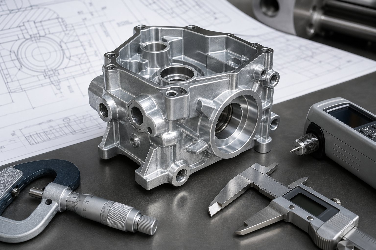
Zinc Die Casting Tolerances
Understanding Zinc Die Casting Tolerances: Industry Standards & Surface Finishes
Zinc die casting produces parts with specific dimensional limits and surface quality requirements.
Die casting tolerances define how much a part’s dimensions can vary from the design specification, whilst surface finish standards determine the smoothness and appearance of the cast surface.
Understanding these two factors helps you make better decisions about part design, manufacturing costs, and final product quality.
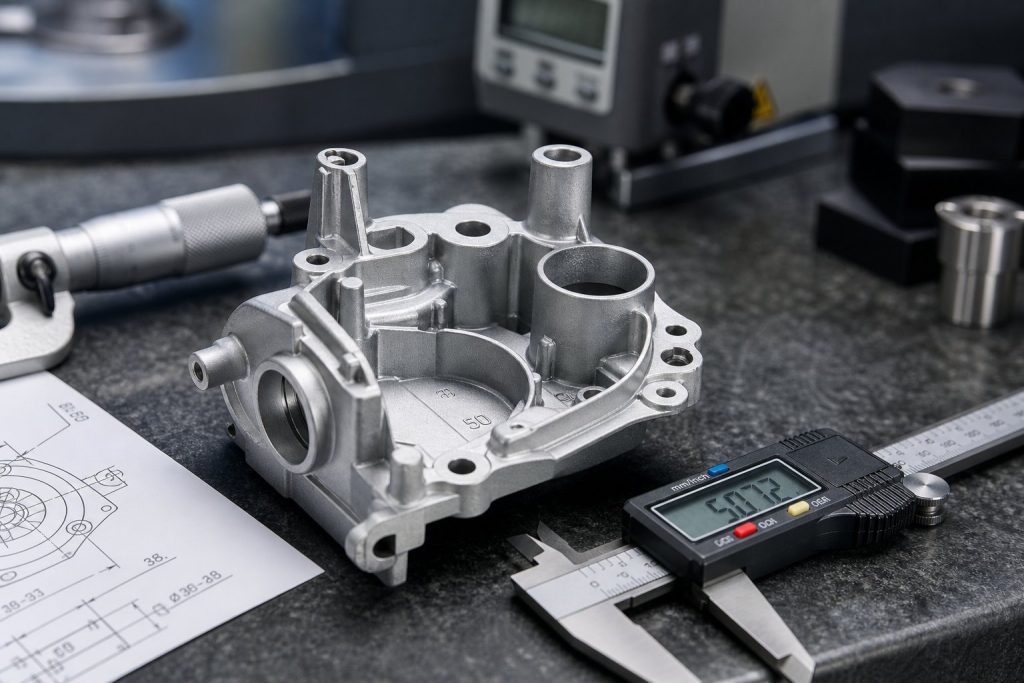
Dimensional accuracy in zinc die casting depends on several factors.
The alloy you choose, the die design, and the casting process all affect how precise your parts will be.
Zinc offers advantages for precision die casting because it flows well into moulds and shrinks less than other metals.
This gives you better dimensional stability and tighter tolerances compared to aluminium or magnesium castings.
Getting the right tolerances and surface finish requires knowledge of industry standards and how different variables impact your results.
You need to balance design requirements with manufacturing capabilities.
This guide walks you through the fundamentals of zinc die casting tolerances, explains how material selection affects quality, and shows you practical ways to maintain precision in production.
Fundamentals of Zinc Die Casting Tolerances
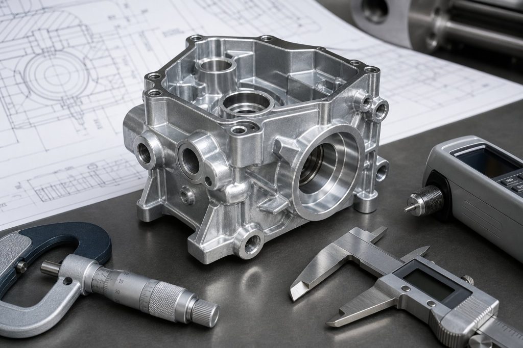
Zinc die casting achieves dimensional tolerances between ±0.05 mm and ±0.2 mm depending on feature size.
Established NADCA standards provide clear guidelines for both linear and geometric specifications.
Understanding these fundamentals helps you specify appropriate tolerances for your components whilst balancing cost and functionality.
Defining Linear and Geometric Tolerances
Linear tolerances measure straight-line distances between two points on a cast part.
These include dimensions like length, width, height, and hole diameters.
For zinc die casting, linear tolerances typically range as follows:
| Feature Size | As-Cast Tolerance |
|---|---|
| 0-25 mm | ±0.05 mm |
| 25-50 mm | ±0.08 mm |
| 50-150 mm | ±0.13 mm |
| Over 150 mm | ±0.2 mm |
Geometric tolerances control the shape and orientation of features.
These include flatness, roundness, perpendicularity, and coaxiality.
Your parts benefit from zinc’s low solidification shrinkage of approximately 0.6%, which supports consistent dimensional stability.
Geometric tolerances ensure that holes align properly, surfaces sit flat, and parts fit together in assemblies.
These specifications become critical when you need multiple features to work together without excessive machining.
NADCA Standards and International Guidelines
The North American Die Casting Association provides the primary standards for die casting tolerances.
NADCA standards establish realistic tolerance ranges based on decades of industry data and manufacturing capability studies.
These standards account for material properties, part geometry, and production variables.
You can reference NADCA tolerance charts to determine appropriate specifications for your design.
ISO 9001:2015 quality management systems often incorporate NADCA guidelines for die casting operations.
This combination ensures your parts meet international quality standards whilst maintaining realistic manufacturing expectations.
Many zinc die casting facilities implement statistical process control (SPC) methods to monitor dimensional stability across production runs.
Standard Versus Precision Tolerances
Standard tolerances refer to the as-cast dimensions achievable through normal die casting processes.
These tolerances suit most applications and keep your costs down.
Precision tolerances require tighter dimensional control, typically ±0.01 mm or better.
You achieve these through secondary operations like post machining on critical features.
Not every surface needs precision tolerancing—only functional areas that affect assembly or performance.
Standard casting tolerances work for cosmetic features, mounting bosses, and general geometry.
Precision tolerances apply to bearing surfaces, threaded holes, and mating interfaces.
Your casting tolerance requirements directly impact tooling design and production costs, so specify tighter tolerances only where necessary for part function.
Material Selection: Impact of Zinc Alloys on Tolerance and Surface Quality
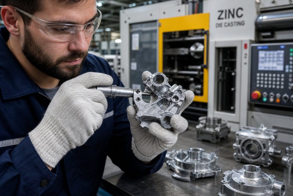
Different zinc alloys deliver distinct mechanical properties and casting behaviours that directly affect dimensional accuracy and surface finish.
ZAMAK 3, ZAMAK 5, and ZA-8 each balance strength, fluidity, and polishability in ways that influence how tightly you can hold tolerances and how smooth your final surface will be.
Properties of Zamak 3, Zamak 5 and ZA-8
ZAMAK 3 serves as the baseline alloy for most zinc die casting applications.
It offers tensile strength around 283 MPa and hardness of approximately 82 HB.
Its balanced fluidity fills thin sections reliably, which supports repeatable dimensions on small features.
The alloy casts with minimal porosity when wall thickness remains uniform, giving you a stable base for plating or powder coating.
ZAMAK 5 adds copper to increase strength to roughly 328 MPa and hardness to 91 HB.
The higher hardness improves wear resistance in parts that see repetitive loads or friction.
You lose some ductility compared to ZAMAK 3, so you need to confirm that assembly stresses and snap fits remain within safe limits.
The alloy maintains good fluidity but requires tighter process control to avoid cosmetic defects on visible faces.
ZA-8 contains higher aluminium content, pushing tensile strength to approximately 374 MPa whilst remaining hot-chamber castable.
This strength step helps when you need structural margin in a compact envelope.
The alloy’s lower fluidity compared to ZAMAK 3 means you should design generous radii and avoid ultra-thin walls.
ZA-8 still finishes well, but your die design and gating must account for the reduced flow.
| Property | ZAMAK 3 | ZAMAK 5 | ZA-8 |
|---|---|---|---|
| Tensile strength (MPa) | ~283 | ~328 | ~374 |
| Hardness (HB) | ~82 | ~91 | ~95 |
| Fluidity | Good | Good | Moderate |
| Polishability | Good | Good | Good |
| Typical use | General-purpose parts | Higher-load components | Structural parts needing strength |
Comparison with Aluminium and Magnesium Die Casting
Zinc alloys melt at lower temperatures than aluminium (around 380–420°C for zinc versus 660°C for aluminium).
This difference reduces die wear and supports longer tool life, which improves dimensional consistency across production runs.
Zinc’s superior fluidity fills fine details and thin walls more reliably than aluminium, letting you hold tighter as-cast tolerances on small features without secondary machining.
Aluminium die casting delivers higher strength-to-weight ratios and better heat resistance, making it the choice when sustained elevated temperatures or significant weight savings drive your design.
However, aluminium’s lower fluidity and higher melting point increase the risk of porosity and warping, which can widen tolerance bands and complicate surface finishing.
Magnesium die casting offers the lowest density of the three but requires cold-chamber equipment and careful environmental control.
Magnesium’s reactivity and oxidation sensitivity add process complexity that can affect surface quality.
Zinc alloys remain more forgiving in production, with stable dimensional behaviour and straightforward finishing paths for plating or coating.
For most small to mid-size parts that need repeatable fits and smooth cosmetic surfaces, zinc alloy die casting provides a practical balance of tolerance capability, surface finish quality, and manufacturing cost.
Influences on Achievable Tolerances in Zinc Die Casting
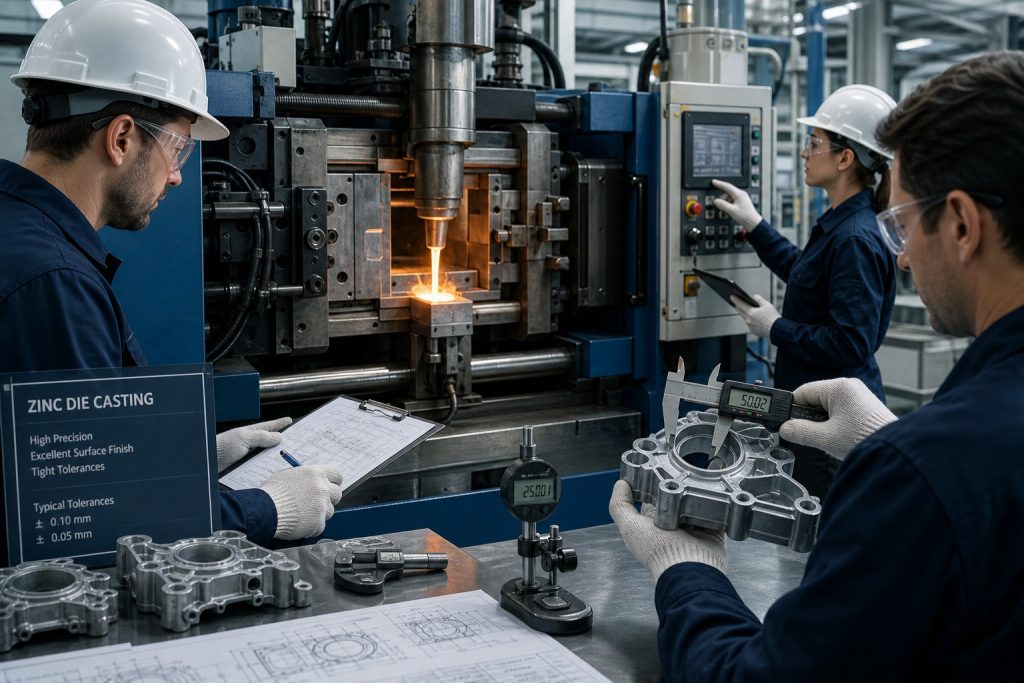
Zinc die casting tolerances depend on several interconnected factors that directly affect dimensional accuracy and production consistency.
Wall thickness uniformity, draft angles, process control measures, and inspection capabilities work together to determine whether you can reliably achieve precision tolerances.
Wall Thickness and Uniformity
Uniform wall thickness stands as one of the most critical factors affecting tolerance capability in zinc die casting.
When wall sections vary by more than 20%, differential cooling rates create internal stresses that cause dimensional distortions and unpredictable shrinkage patterns.
Solidification shrinkage in zinc alloys typically ranges from 0.6% to 0.7%, but non-uniform sections can experience localised variations that exceed these values.
Maintaining consistent wall thickness between 0.75 mm and 3.0 mm provides optimal results for tolerance control.
Thicker sections cool more slowly, creating thermal gradients that pull dimensions away from nominal specifications.
Thinner walls risk incomplete filling and cold shuts that compromise dimensional accuracy.
You should design transitions between different wall thicknesses gradually, using ratios no greater than 1:1.5 to minimise stress concentrations.
Sharp thickness changes create hot spots that prolong cycle time and reduce production efficiency whilst degrading tolerance capability.
Draft Angles and Part Geometry
Draft angles affect both ejection quality and long-term tolerance capability by impacting tooling wear. Minimum draft angles of 1° on vertical surfaces allow clean part removal.
Optimal draft angles of 1.5° to 3° extend tool life and maintain dimensional stability across production runs.
Insufficient draft increases ejection forces, damaging part surfaces and accelerating die wear. This leads to progressive dimensional degradation.
Each ejection cycle without enough draft damages the casting surface and wears the die cavity. Over time, this shifts dimensions outside tolerance bands.
Complex part geometry introduces additional tolerance challenges. Deep ribs, undercuts, and intricate features require slides, lifters, or collapsing cores.
Each extra tool movement can cause tolerance stack-up and increase maintenance needs. This affects dimensional consistency.
| Geometry Feature | Minimum Draft | Optimal Draft | Tolerance Impact |
|---|---|---|---|
| External surfaces | 1° | 2-3° | Baseline |
| Internal surfaces | 1.5° | 3-4° | +0.02 mm variance |
| Deep pockets | 2° | 3-5° | +0.03 mm variance |
| Textured surfaces | 3° | 5-7° | +0.05 mm variance |
Process Control and Tooling Quality
Process control parameters determine if your zinc die casting operation can maintain precision tolerances across high-volume production. Shot velocity, die temperature, and intensification pressure must stay within tight limits to achieve consistent dimensional accuracy.
Die temperature variations greater than ±3°C cause non-uniform solidification and dimensional inconsistencies. Modern operations use conformal cooling channels and real-time temperature monitoring to optimize thermal control.
Statistical process control systems track critical parameters and alert you before process drift produces out-of-specification parts.
Tooling quality forms the foundation for tolerance achievement throughout production. H13 tool steel with a hardness of 46-50 HRC provides optimal wear resistance under cyclic thermal loading.
Premium tool construction costs 40-60% more than standard tooling but delivers consistent tolerance capability over extended production volumes.
Regular tooling maintenance prevents dimensional degradation from accumulated wear. Inspection schedules should include cavity dimension verification and ejector pin condition assessment.
Cooling channel flow testing also helps maintain tolerance control.
Inspection and Metrology Methods
First article inspection verifies that tooling and process parameters can achieve specified tolerances before full production begins. Measure all critical dimensions using calibrated equipment with measurement uncertainty ratios of at least 10:1 relative to the tolerance band.
CMM capabilities must match your tolerance requirements. For zinc die castings with tolerances of ±0.08 mm, CMM systems with accuracy of ±0.008 mm or better are necessary for reliable dimensional verification.
Contact measurement methods work well for most features. Non-contact optical systems handle complex geometries without deflection concerns.
In-process monitoring allows real-time adjustments to maintain tolerance compliance throughout production runs. Automated dimensional checking systems integrated with die casting controls provide immediate feedback on dimensional trends.
You can implement corrective actions before significant numbers of non-conforming parts accumulate.
Key metrology considerations:
- Measurement frequency based on process capability indices
- Environmental control maintaining 20°C ±2°C for precision measurement
- Fixturing that replicates functional datum references
- Statistical sampling plans appropriate to production volume
Die Casting Processes and Their Effect on Tolerance Outcomes
The choice between hot chamber and cold chamber methods shapes dimensional precision. High-pressure and squeeze casting techniques each deliver distinct tolerance characteristics.
Production consistency relies on cycle control and systematic maintenance rather than just end-of-line inspection.
Hot Chamber Versus Cold Chamber Methods
Hot chamber die casting is the standard method for zinc alloys due to their low melting point of 419°C. The machine’s injection mechanism stays submerged in molten metal, enabling rapid cycles and precise shot control.
This direct contact with the melt keeps injection speeds and pressures highly consistent between cycles, which reduces dimensional variation.
You’ll achieve tighter tolerances with hot chamber processes because shot-to-shot consistency is superior. Rapid injection and short cycle times minimize temperature fluctuations in the die, helping you hold ±0.05 mm on small features with good process control.
Cold chamber die casting requires manually ladling molten metal into the injection chamber for each shot. This method suits higher-melting alloys like aluminium but is rarely used for zinc.
The extra handling introduces more variables, such as melt temperature fluctuations, inconsistent fill rates, and longer cycles. These factors widen tolerances and reduce repeatability compared to hot chamber methods.
Your die casting manufacturer will usually recommend hot chamber services for zinc components when you need high-volume production with minimal tolerance drift.
High-Pressure and Squeeze Casting Processes
High-pressure die casting injects molten zinc at 10–175 MPa, forcing the material into every detail of the die cavity. This pressure ensures complete fill of thin walls and intricate features while minimizing porosity.
The result is dense, dimensionally stable parts that hold tolerances well without extra operations. Injection pressure directly affects how tightly you can control dimensions.
Higher pressures compact the metal more thoroughly, reducing shrinkage variation and improving surface finish. Excessive pressure can increase flash at parting lines if die clamping force isn’t sufficient.
Squeeze casting applies pressure during solidification rather than just injection. This method reduces porosity further and can improve mechanical properties, but it’s less common for zinc than aluminium.
Cycle times increase with squeeze casting, raising production costs. For most zinc components, standard high-pressure die casting provides adequate density and tolerance control without extra expense.
Vacuum assist removes air from the die cavity before injection. This reduces gas porosity and allows thinner walls without defects, improving both dimensional consistency and surface quality.
Production Cycle and Maintenance Considerations
Your production cycle must balance injection speed, melt temperature, and die temperature to maintain repeatable tolerances. Zinc’s fast solidification allows cycle times as short as 15–30 seconds.
Rushing cycles without proper thermal equilibrium causes dimensional drift. Consistent die temperature (typically ±5°C) is essential.
Uneven heating causes thermal expansion differences across the cavity, distorting part geometry. Die temperature controllers and enough warm-up time before production starts help you avoid this variation.
Preventive maintenance schedules preserve tolerance stability over thousands of shots. Parting line wear, core pin erosion, and ejector damage all gradually widen tolerances.
Shops that perform regular die inspections, refurbishment, and polishing deliver more consistent parts. Monitoring injection pressure, shot weight, and cycle time as process indicators helps maintain quality.
Statistical process control charts reveal trends before parts go out of specification. This upstream focus reduces scrap and keeps production costs predictable over long runs.
Surface Finish Specifications for Zinc Die Castings
Zinc die castings can achieve different surface finish grades depending on your application requirements. The finish you choose affects both appearance and functional properties like corrosion resistance and wear performance.
As-Cast, Polished, and Plated Surfaces
As-cast surfaces come directly from the die without extra processing. These surfaces usually show some roughness from the casting process, with roughness values that vary based on mould conditions and metal temperature control.
Casting zinc alloy at 400°C-450°C with proper mould temperature gives you better as-cast surface quality. Polishing reduces surface roughness through mechanical finishing.
Belt grinding can achieve roughness values from Ra 1 (with 60 grit) down to Ra 0.1 (with 2400 grit). Bobbing after grinding further reduces roughness to Ra 0.01 to 0.25 and removes grinding marks.
Vibratory finishing offers another option for deburring and polishing, achieving Ra 0.01 to 0.3. However, it has limitations with small internal areas.
Plated surfaces require a base metal layer before decorative plating. Copper plating serves as the initial layer, followed by nickel for improved corrosion resistance and wear properties.
Chromium plating provides the final decorative layer and enhances hardness and friction resistance. You can also specify electroless nickel-phosphorous for superior hardness and anti-corrosion performance without the copper-nickel undercoat.
Coating Types: Powder Coating, Painting, and Chromate Conversion
Powder coating offers excellent corrosion protection and decorative options for zinc castings. Epoxy powder coatings suit interior applications with moderate durability needs.
Epoxy-polyester blends offer better anticorrosion performance for outdoor use. Polyester powder coatings provide the highest UV resistance and corrosion protection for harsh environments like coastal or industrial settings.
Painting options include wet paint and electrophoretic paint systems. Polyurethane wet paint achieves good decoration and anticorrosion properties.
Electrophoretic paint offers superior coverage and corrosion resistance, especially for complex geometries. Both methods allow color coding and aesthetic customization while protecting against corrosion.
Chromate conversion coating is a chemical passivation treatment that provides anticorrosion properties without adding significant thickness. This process creates a thin protective layer directly on the zinc surface.
It works well as a standalone finish for utility applications or as a pre-treatment before painting or powder coating.
Quality Signals and Defect Detection
Surface defects affect both appearance and performance. Common issues include porosity, cold shuts, and flow lines that appear during casting.
Shot blasting or grit blasting helps reduce these surface defects before applying finish coatings. Blistering occurs when trapped gases or moisture react with coatings during curing.
This defect signals inadequate surface preparation or contamination. You prevent blistering through proper cleaning, complete drying, and controlled coating application temperatures.
Inspection focuses on surface roughness measurements, coating thickness verification, and visual checks for defects. Belt grinding marks should be removed by bobbing before final finishing.
Areas not accessible to mechanical finishing may require chemical treatments or remain as-cast depending on your specifications.
Best Practices for Maintaining Tolerances and Surface Integrity
Maintaining tight tolerances and surface integrity in zinc die casting requires careful defect prevention and proper secondary operations. Compliance with established standards ensures your parts meet specifications and minimizes rework and scrap rates.
Defect Prevention and Process Monitoring
Preventing casting defects starts with proper design for manufacturability (DFM) principles. Design adequate venting into your dies to prevent air entrapment, which causes porosity and cold shuts.
Carefully place the parting line to minimise flash formation and maintain dimensional accuracy.
Process monitoring during production helps catch issues before they affect tolerances. Control metal temperature, injection pressure, and cycle times consistently.
Monitor die temperature throughout production runs because thermal expansion affects dimensional accuracy.
Common defects that impact tolerances include:
- Porosity – trapped gas or shrinkage voids that weaken parts
- Warpage – distortion from uneven cooling or part geometry
- Cold shut – incomplete metal fusion creating weak seams
- Flash – excess material at parting lines requiring removal
Regularly inspect the first articles and sample parts during production runs. Adjust process parameters before defects accumulate.
Maintain a die maintenance schedule to prevent wear patterns that degrade tolerances over time.
Secondary Operations and Post-Casting Machining
Secondary machining becomes necessary when required tolerances exceed standard precision die casting capabilities. Identify machined features during the design phase to ensure enough stock material remains after casting.
Trimming removes flash and excess material from the parting line. This operation improves surface finish and brings parts within tighter dimensional specifications.
CNC machining adds precision features like threaded holes, tight-tolerance bores, or flat mounting surfaces.
Plan your secondary operations strategically:
- Determine which features need machining versus as-cast surfaces
- Allow appropriate machining stock (typically 0.25-0.5mm)
- Design locating features for consistent work holding
- Specify tolerances appropriate to each manufacturing method
Minimise secondary operations through effective DFM to reduce costs. Some applications require machined features to achieve necessary precision or surface finish beyond as-cast capabilities.
Adhering to NADCA and International Standards
NADCA standards provide industry-accepted tolerance guidelines for die casting. These standards specify achievable dimensional tolerances based on part size, feature type, and alloy selection.
Reference NADCA’s Product Specification Standards when establishing your tolerance requirements.
Standard tolerances accommodate normal process variation. Precision die casting achieves tighter specifications through enhanced process control and tooling.
Your specifications need to match what’s achievable without excessive cost.
For automotive applications, IATF 16949 certification ensures your supplier maintains quality management systems for critical components. This standard requires documented process control, traceability, and continuous improvement.
NADCA guidelines cover:
- Linear dimensional tolerances by part size
- Geometric dimensioning and tolerancing (GD&T) applications
- Draft angle requirements
- Surface finish specifications
- Inspection and quality assurance procedures
Following these standards ensures consistency between suppliers and provides clear communication of your requirements.
Frequently Asked Questions
Zinc die casting can reliably hold tolerances of ±0.025 to ±0.05 mm on small precision components within a single die half. As-cast surface finish typically ranges from 1.0 to 2.5 μm Ra, while machining or polishing after casting achieves tighter geometric controls and smoother finishes.
What dimensional tolerances are typically achievable with zinc die casting for small precision components?
For features formed entirely within one die half, zinc die casting can hold tolerances as tight as ±0.025 mm (±0.001″) to ±0.05 mm (±0.002″) on the first 25 mm of length. This represents NADCA Precision-grade capability and applies to small parts where both ends of the dimension are formed by the same piece of tooling steel.
Zinc holds tighter tolerances than aluminium or magnesium because it has lower shrinkage during cooling and a lower melting temperature. The metal fills thin sections cleanly and puts less thermal stress on the die.
Features that cross the parting line carry looser tolerances. Add parting line separation tolerance (typically +0.13 mm on the high side only) and parting line shift tolerance (typically ±0.10 mm added evenly).
A dimension that would be ±0.05 mm within one die half becomes roughly -0.05 / +0.18 mm when it crosses the parting line.
Moving slides add even more tolerance stack. A feature formed by a slide can drift an additional ±0.15 mm depending on the projected area of the slide and the hydraulic clamping force.
If you need a tight dimension on a slide feature, machine it after casting.
Tolerances tighter than ±0.025 mm almost always require secondary CNC machining. The casting process alone cannot hold ±0.01 mm repeatably across thousands of shots.
How should ISO 8062 and ISO 8062-3 be applied when specifying tolerances for zinc die cast parts?
ISO 8062-3 uses CT (Casting Tolerance) grades to define allowable dimensional variation. The grades run from CT1 (tightest) to CT16 (loosest).
For high-pressure zinc die casting, normal production falls within CT4 to CT6.
CT4 is roughly equivalent to NADCA Precision tolerances. CT6 is roughly equivalent to NADCA Standard tolerances.
If your supply chain spans multiple regions, put both the ISO CT grade and the NADCA grade on your drawing to avoid confusion during quoting.
ISO 8062-3 defines tolerances based on the basic size of the feature. A 50 mm linear dimension held to CT5 would carry a tolerance of approximately ±0.17 mm.
The same dimension held to CT4 would be approximately ±0.11 mm.
Specify the DCTG (General Dimensional Casting Tolerance Grade) separately from specific feature callouts. The DCTG sets the default tolerance for any dimension not otherwise specified.
Most zinc die castings use DCTG-4 or DCTG-5.
When you write the drawing note, use this format: “General tolerances per ISO 8062-3 DCTG-5 unless otherwise specified.” Call out tighter CT grades only on features that need them, such as mating surfaces or locating datums.
Which factors most strongly influence tolerance capability in zinc die casting, including tool design and process variation?
Die design is the single largest factor. A well-designed die with robust steel sections, proper venting, and tight guide pins holds closer tolerances over more shots than a poorly designed one.
Guide pin wear causes parting line shift, which directly opens up the tolerance window on any dimension that crosses the parting line.
Part geometry matters nearly as much. Thin unsupported walls warp during cooling.
Thick sections shrink unevenly and create internal stresses that distort the part after ejection. Ribs, gussets, and uniform wall thickness stabilise the casting and reduce dimensional drift.
Alloy shrinkage rate affects the final size. Zamak 3 shrinks about 0.8 to 1.2% during cooling.
If the die designer does not compensate correctly in the tooling, every feature will measure undersized by that percentage. Shrinkage variation between batches of alloy also causes shot-to-shot size variation.
Injection parameters add another layer of variation. Higher injection pressure packs more metal into the cavity and pushes the die halves apart slightly.
Lower pressure reduces flash but can leave the part undersized. Die temperature, fast shot speed, and hold time all influence how the metal fills and solidifies.
Tool maintenance keeps tolerances consistent. A worn die with damaged vents, eroded gate areas, or loose slides will drift outside tolerance long before the die reaches its rated shot life.
Preventive maintenance every 50,000 to 100,000 shots keeps dimensions stable.
What surface finish levels can be expected from zinc die casting as-cast, and when is secondary finishing required?
As-cast zinc die castings typically deliver a surface finish of 1.0 to 2.5 μm Ra (arithmetical mean roughness). This finish is smooth enough for many functional applications and is better than sand casting or gravity die casting without machining.
The finish depends on die surface condition and alloy cleanliness. A freshly polished die produces the smoothest parts.
After several thousand shots, micro-erosion from molten metal flow roughens the die surface, and the casting surface roughness increases.
If you need a finish smoother than 1.0 μm Ra, add secondary operations. Vibratory finishing, barrel tumbling, or bead blasting can bring the finish down to around 0.8 μm Ra while slightly rounding sharp edges.
CNC machining can deliver 0.4 to 0.6 μm Ra on critical surfaces like sealing faces or bearing bores.
Polishing is required for decorative parts or surfaces that will be plated. A rough casting surface will show through the plating layer and look uneven.
Manual polishing can achieve 0.1 to 0.2 μm Ra but adds significant cost and lead time.
For cosmetic parts, specify different finishes on different surfaces. A hidden mounting boss might be acceptable at 2.5 μm Ra as-cast, while a visible exterior face gets polished to 0.4 μm Ra before chrome plating.
This approach balances appearance with cost.