
Die Casting Dies: What Engineers Should Decide Before Tooling Starts
Die casting dies are precision tools that form molten metal into a repeatable component. Their design affects far more than the shape of the finished casting: it influences how metal enters the cavity, how air escapes, how heat is managed, how the casting is released and which marks remain on visible surfaces. For engineers and buyers, the best time to resolve these points is before tooling manufacture begins.
This guide explains the decisions to make before commissioning tooling for a zinc die-casting project. The correct solution still depends on the component, selected alloy, production requirements and agreed acceptance criteria.
Key takeaways
- A die must form the component, route metal into the cavity, manage air and heat, and release the solidified casting without unacceptable distortion or damage.
- Parting lines, draft, ejector locations, runners, gates, vents and any moving cores should be considered with the component design, rather than added after it is frozen.
- Cosmetic surfaces, critical dimensions, secondary operations and assembly requirements need to be identified before the die layout is approved.
- Tool cost and tool life cannot be judged from part size alone. Geometry, die construction, material choice, thermal conditions, maintenance and the required output all matter.
- Early collaboration between the product designer, die caster, toolmaker and finishing or assembly specialists reduces avoidable redesign.
What is a die in die casting?
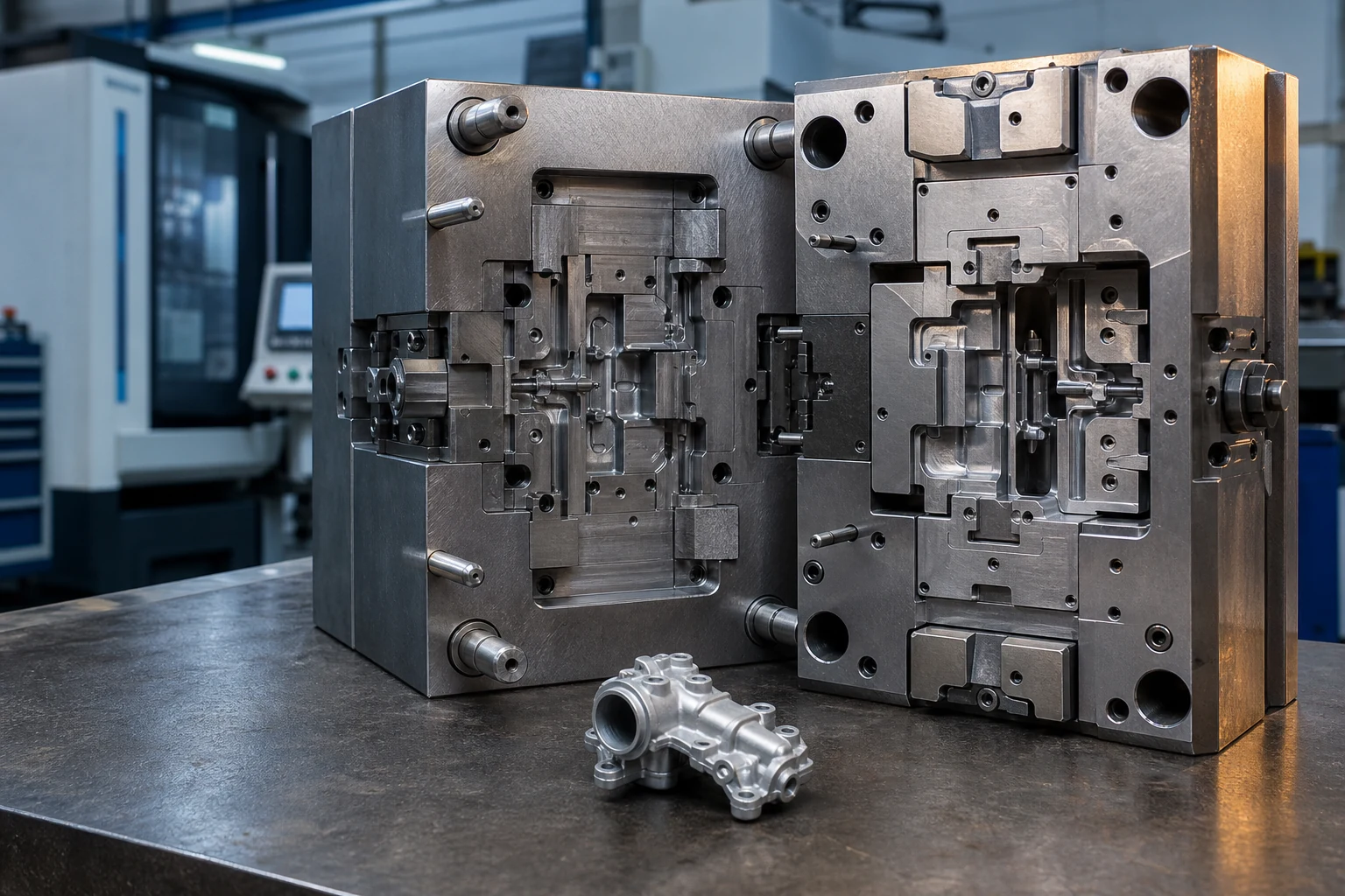
Die casting dies are reusable metal tools containing the cavities that give components their shape. A basic die has a stationary half and a moving, or ejector, half. It also includes a route for metal to reach the cavity and features that allow the casting to be removed after solidification.
Real tooling may include cavity inserts, runners, gates, vents, overflow areas, ejector pins, cooling or heating channels and moving cores or slides. The exact arrangement is project-specific. A feature that appears simple on a component drawing can have a significant effect on die construction if it creates an undercut, prevents straight ejection or requires a moving element.
The North American Die Casting Association’s technical FAQ describes four linked considerations in die design: metal flow, venting, thermal management and ejection. For a UK project, those principles should be applied alongside the customer’s drawing requirements, applicable standards and the die caster’s validated process knowledge.
Why the component and die should be designed together
Die casting dies cannot correct every problem in a finished component design. The component determines where the two die halves can separate, which surfaces need draft, where the casting can grip the tool and whether a feature can be formed in the direction of die movement.
The International Zinc Association recommends involving the designer, alloy supplier, die caster, toolmaker and relevant secondary-operation specialists during development. Its zinc die-casting design guidance explains that die retention and ejection features can affect the component itself. This is why design for manufacture should happen before drawings are released for final tooling.
Early review of die casting dies also helps separate functional requirements from inherited drawing details. Challenging those details can simplify tooling without changing what the product needs to do.
Eight decisions to resolve before tooling starts
1. Define the component’s function and acceptance criteria
Begin with what the component must do in its assembly. Identify interfaces, loads, environmental exposure, electrical or thermal requirements, visible surfaces and any regulatory or customer specifications. Mark critical dimensions and explain why they are critical. A toolmaker can make better trade-offs when the functional reason is clear.
Agree how the first-off castings will be assessed. The drawing revision, datum strategy, inspection plan, surface requirements and approval responsibilities should refer to the same controlled information. Do not leave these decisions until a trial casting is on the bench.
2. Agree the parting line
The parting line is where the die halves meet, and it normally leaves a visible witness on the casting. Its position affects die construction, trimming, dimensional relationships and appearance. The International Zinc Association’s design rules for zinc die castings advise placing the parting line with the component geometry and visible surfaces in mind.
A simple, accessible parting line is generally easier to control than one that steps around several features. That does not make a flat line mandatory, but any added complexity should solve a defined functional or cosmetic problem.
3. Provide a practical release direction and draft
Surfaces parallel to the die opening direction can resist release. Draft gives them a slight taper so the casting can leave the cavity. The amount and direction must be reviewed with the chosen geometry, depth, surface texture and process. Avoid applying a generic draft value without the die caster’s confirmation.
Ask the toolmaker to show the proposed pull direction on the model. This quickly reveals reverse draft, trapped details and areas that may need a slide, core or design change.
4. Control section changes, corners and ribs
More metal is not automatically better. Abrupt changes between thick and thin sections can make filling and solidification harder to manage. Gradual transitions and radiused internal corners are usually more helpful to flow and tool manufacture than sharp changes.
Ribs can add stiffness without thickening a whole wall, but their height, thickness, spacing and junctions still need review. The aim is a coherent casting that fills and releases reliably, not the largest possible number of reinforcing features.
5. Decide how holes, undercuts and side features will be made
A hole aligned with die movement may be suitable for coring. A side hole, return or undercut can require moving tooling or a secondary operation. Each approach has consequences for tool complexity, cycle sequence, maintenance, positional relationships and unit processing.
Do not assume every detail must be cast. Compare a tool feature with drilling, tapping or another secondary operation across the expected programme. Jones & Wilkinson lists tapping, drilling and CNC machining among its current secondary operations, but the appropriate route must be confirmed for the particular component.
6. Identify cosmetic and finishing requirements
Mark the surfaces the customer will see and the areas where a gate, ejector witness or parting line would be unacceptable. State whether the part is used as cast or receives another finish. Surface expectations can influence gate position, die surface preparation, handling and later operations.
If components will be plated, polished or powder coated, involve the finishing specialist before tool approval. The die caster needs to understand which surfaces matter and which casting features are needed for handling or assembly. Jones & Wilkinson’s website states that it can coordinate finished-part assembly; project-specific finishing and assembly requirements should still be agreed in writing.
7. Supply reliable CAD and drawing data
Provide a controlled 3D model and a drawing that identifies material specification, critical dimensions, datums, threads, inserts, finishes and revision status. Resolve discrepancies between the model and drawing before die manufacture. A notes field saying “to CAD” is not enough if the drawing contains conflicting dimensions.
Include the mating components or interface information where they affect fit. Tooling decisions are stronger when the supplier can see the assembly context rather than an isolated part.
8. Define programme and ownership requirements
Explain the expected production profile, service requirements and change-control process without forcing an unsupported guarantee. Ask who owns the die and CAD data, where the tool will be stored, how maintenance will be recorded, which changes require approval and what happens if a component revision is proposed.
Tool life is a project-specific engineering and commercial matter. It should not be promised from a generic material comparison or a single cycle figure.
How design choices affect the tooling route
| Design decision | Why it matters to the die | Question to settle before approval |
|---|---|---|
| Parting line | Sets how the die separates and where a witness may remain. | Is the witness acceptable on the proposed surfaces? |
| Undercuts and side holes | May require moving cores, slides or a separate operation. | Should the feature be cast, redesigned or machined later? |
| Visible surfaces | Influence gate, ejector and parting-line placement. | Which faces have a defined cosmetic requirement? |
| Wall and rib layout | Affects filling, solidification, stiffness and release. | Can transitions be made more gradual without losing function? |
| Critical dimensions | Affect datum planning, die construction and inspection. | Which dimensions control fit, and how will they be verified? |
| Finishing and assembly | May require handling, masking, location or joining features. | Have downstream suppliers reviewed the proposed casting? |
How die casting dies are developed
The detailed sequence varies, but a sound tooling project normally moves through linked review, design, manufacture and validation stages.
Design-for-manufacture review
Before die casting dies are released for manufacture, the die caster and toolmaker review the model, drawing and application. They identify the die opening direction, parting line, areas needing draft, potential moving elements, likely gate and ejector locations, and details that may be better produced later. Open points should be recorded and resolved with the customer.
Die layout and process features
The toolmaker develops the cavity arrangement and the systems needed to fill, vent, thermally manage and eject the casting. These systems interact: changing a gate position can affect flow, the location of a witness and the available space for other tool features.
Manufacture and assembly
Components for die casting dies are manufactured using appropriate machining and toolmaking processes, then fitted and checked as an assembly. Jones & Wilkinson’s current toolmaking service lists tool design, 3D CNC with CAD, EDM, CAD/CAM and prototyping in its in-house toolroom. Those are verified company-wide capabilities; the route for any individual die remains subject to technical review.
Trial, inspection and correction
Trial castings provide evidence for the agreed approval checks. The team reviews dimensions, filling, visible surfaces, trimming, ejection and any downstream operations relevant to the specification. Adjustments should be controlled, documented and assessed against the approved drawing rather than judged only by appearance.
Questions to ask a die caster and toolmaker
When comparing suppliers for die casting dies, use these questions to test how each team approaches design, approval and long-term tool support.
- Which part features are most likely to complicate filling, release or die construction?
- Where are the proposed parting line, gates and ejector witnesses?
- Which holes or undercuts should be cast, and which should be produced as secondary operations?
- What customer information is still needed before the tool design can be approved?
- How will drawing revisions and customer approvals be controlled?
- Which trial parts and inspection records will be supplied for approval?
- How will routine maintenance, repairs and tooling changes be recorded?
- Which finishing or assembly suppliers should review the design before tooling release?
When zinc die casting may not be the right route
A good supplier should identify when the component or programme does not suit its verified process capability. Tooling investment needs a credible production case. Very low demand, difficult undercuts, requirements better served by machining or fabrication, or an incompatible material specification can point elsewhere.
Do not select a process from one headline benefit. Compare functional performance, tooling, unit processing, finishing, inspection, assembly and change risk across the expected programme. Jones & Wilkinson’s zinc die-casting service can form part of that discussion, but suitability must be established from the drawing and manufacturing requirements.
Frequently asked questions about die casting dies
What is the difference between a die and a mould?
Both terms describe tooling that forms a part, but “die” is the normal term for pressure die casting. “Mould” is more commonly associated with processes such as plastic injection moulding. Using the correct term helps keep discussions and specifications clear.
What are the main parts of a die-casting die?
Most die casting dies have stationary and ejector halves, a cavity, a metal-delivery route and an ejection system. Depending on the component, it may also use inserts, vents, overflow areas, thermal-control channels, cores or slides.
Why does the parting line matter?
It determines how the die separates and normally leaves a witness on the casting. Its position can also affect trimming, dimensional relationships, tool complexity and the appearance of the finished component.
Can threads and holes be formed in the die?
Some features may be cored, while others are better drilled, tapped or machined after casting. Direction, depth, access, required accuracy, tool complexity and programme economics all affect the decision.
How long does a die-casting die last?
There is no responsible universal figure. Die material and heat treatment, alloy, component geometry, thermal conditions, die design, operating practice, maintenance and acceptance requirements all influence service life. Ask for a project-specific basis and clearly defined commercial terms.
Who should approve a die design?
The customer’s authorised engineer should approve the component and agreed interfaces, while the die caster and toolmaker take responsibility for the manufacturing design within their scope. Finishing, secondary-operation and assembly specialists should review features that affect their work.
What information is needed for a tooling review?
Supply the current 3D model and drawing, material and finish requirements, critical dimensions and datums, expected production profile, mating-part information, inspection expectations and any applicable customer or regulatory specifications.
Plan tooling around the whole component
Effective die casting dies begin with a component reviewed for filling, release, finishing, inspection and assembly. Resolve these requirements while the design can still change and document the decisions.
Jones & Wilkinson has supported zinc die-casting and toolmaking projects since 1965. To discuss a new component, existing tooling or a drawing that needs a design-for-manufacture review, contact the team with the available project information. The drawing, specification and intended programme will be reviewed before any manufacturing route is confirmed.


